Note: This document is for an older version of GRASS GIS that has been discontinued. You should upgrade, and read the current manual page.
NAME
ps.map - Produces hardcopy PostScript map output.KEYWORDS
postscript, printingSYNOPSIS
Flags:
- -r
- Rotate plot 90 degrees
- -p
- List paper formats (name width height left right top bottom(margin))
- -e
- Create EPS (Encapsulated PostScript) instead of PostScript file
- -b
- Describe map-box's position on the page and exit (inches from top-left of paper)
- --overwrite
- Allow output files to overwrite existing files
- --help
- Print usage summary
- --verbose
- Verbose module output
- --quiet
- Quiet module output
- --ui
- Force launching GUI dialog
Parameters:
- input=name [required]
- File containing mapping instructions
- Use '-' to enter instructions from keyboard)
- output=name [required]
- Name for PostScript output file
- copies=integer
- Number of copies to print
- Options: 1-20
Table of contents
DESCRIPTION
ps.map is a cartographic mapping program for producing high quality hardcopy maps in PostScript format. Output can include a raster map, any number of vector overlays, text labels, decorations, and other spatial data.A file of mapping instructions that describes the various spatial and textual information to be printed must be prepared prior to running ps.map.
NOTES
The order of commands is generally unimportant but may affect how some layers are drawn. For example to plot vpoints above vareas list the vpoints entry first. Raster maps are always drawn first, and only a single raster map (or 3 if part of a RGB group) may be used.The hash character ('#') may be used at the beginning of a line to indicate that the line is a comment. Blank lines will also be ignored.
Be aware that some mapping instructions require the end command and some do not. Any instruction that allows subcommands will require it, any instruction that does not allow subcommands will not.
The resolution and extent of raster maps plotted with ps.map are controlled by the current region settings via the g.region module. The output filesize is largely a function of the region resolution, so special care should be taken if working with large raster datasets. For example if the desired output is US-Letter sized paper at 600dpi, with 1" margins and the raster filling the entire page, the usable area on the page will be 6.5" x 9", which at 600 dots/inch is equivalent to a region of 3900 columns x 5400 rows (see "g.region -p"). Any higher resolution settings will make the output file larger, but with a consumer printer you probably won't be able to resolve any better detail in the hardcopy.
The user can specify negative or greater than 100 percentage values for positioning several map decorations and embedded EPS-files, to move them outside the current map box region (for example to position a caption, barscale, or legend above or below the map box).
One point ("pixel") is 1/72 of an inch.
For users wanting to use special characters (such as accented characters) it is important to note that ps.map uses ISO-8859-1 encoding. This means that your instructions file will have to be encoded in this encoding. If you normally work in a different encoding environment (such as UTF-8), you have to transform your file to the ISO-8859-1 encoding, for example by using the iconv utility:
iconv -f UTF-8 -t ISO_8859-1 utf_file > iso_file
MAPPING INSTRUCTIONS
The mapping instructions allow the user to specify various spatial data to be plotted. These instructions are normally prepared in a regular text file using a system editor. Some instructions are single line instructions while others are multiple line. Multiple line instructions consist of the main instruction followed by a subsection of one or more additional instructions and are terminated with an end instruction.
Instruction keywords:
[ border | colortable | comments | copies | eps | geogrid | greyrast | grid | group | header | labels | line | mapinfo | maploc | maskcolor | outline | paper | point | psfile | raster | read | rectangle | region | rgb | scale | scalebar | setcolor | text | vareas | vlines | vpoints | vlegend | end ]Common instructions
Instructions that may be included in the subsection under several different main instructions are:- where x y
- The top left corner of the bounding box of the item to be plotted is located x inches from the left edge of the paper and y inches from the top edge of the paper. If x is less than or equal to zero, the default horizontal location is used. If y is less than or equal to zero, the default vertical location is used.
- font font name
- The name of the PostScript font.
Fonts present in all PostScript implementations are:
Times-Roman,
Times-Italic,
Times-Bold,
Times-BoldItalic,
Helvetica,
Helvetica-Oblique,
Helvetica-Bold,
Helvetica-BoldOblique,
Courier,
Courier-Oblique,
Courier-Bold,
and
Courier-BoldOblique.
The default is Helvetica. - fontsize font size
- The size of the PostScript font (in 1/72nds of an inch). The default is 10 point.
- color name
- The following colors names are accepted by ps.map:
aqua,
black,
blue,
brown,
cyan,
gray,
grey,
green,
indigo,
magenta,
orange,
purple,
red,
violet,
white,
yellow
.
For vectors and some plotting commands you can also specify 'none' or 'R:G:B' (e.g '255:0:0'). - yes|no
- For options that take a yes or no answer, you can simply use the letters "y" or "n", or type out the full words "Yes" or "No" if you prefer. It is not case-sensitive. Typically the option with have a default answer and you only need to specify one if you wish to override it.
Command usage
border
Controls the border which is drawn around the map area.USAGE: border [y|n] color color width # end
The border can be turned off completely with the "border n" instruction. In this case the end command should not be given as the main command will be treated as a single line instruction.
This example would create a grey border 0.1" wide.
EXAMPLE:
	border
	color grey
	width 0.1i
	end
colortable
Prints the color table legend for the raster map layer anywhere on the page.USAGE: colortable [y|n] where x y raster raster map range minimum maximum width table width height table height (FP legend only) cols table columns font font name fontsize font size color text color nodata [Y|n] tickbar [y|N] discrete [y|n] end
If raster is omitted, the colortable defaults to the previously registered raster layer.
The default location for the colortable is immediately below any other map legend information, starting at the left margin. The default text color is black.
Omitting the colortable instruction would result in no color table. If the colortable is turned off with a "colortable N" instruction the end command should not be given as the main command will be treated as a single line instruction.
See also the vlegend command for creating vector map legends.
Categorical (CELL) Maps
Adding the nodata N instruction will prevent the "no data" box from being drawn (category based legends only). If you have manually added a "no data" label to the cats/ file it will be shown regardless.Note: Be careful about asking for color tables for integer raster map layers which have many categories, such as elevation. This could result in the printing of an extremely long color table! In this situation it is useful to use the discrete N instruction to force a continuous color gradient legend.
Be aware that the color table only includes categories which have a label. You can use the r.category module to add labels.
Floating point (FCELL and DCELL) Maps
The legend's range can be adjusted for floating point rasters, but if set beyond the extent of the map's range be sure that you have set up color rules with r.colors which cover this range. If the map has been given a data-units label with r.support then this label will be displayed. For floating point legends width is width of color band only. height is used only for floating point legend. A horizontal gradient legend can be achieved by setting the legend width greater than its height. Adding the tickbar Y instruction will change the tick mark style so that ticks are drawn across the color table instead of protruding out to the right (floating point legends only). Adding the discrete Y instruction will command the program to treat the map as a categorical map. In this way the legend can be created with discrete range bands instead of a continuous gradient. You must use the r.category or r.support module to set up the range labels first.This example would print a color table immediately below any other map legend information, starting at the left margin, with 4 columns:
EXAMPLE:
	colortable y
        cols 4
        width 4
        end
comments
Prints comments anywhere on the page.USAGE: comments commentfile where x y font font name fontsize font size color text color end
If you wish to use parentheses spanning multiple lines you will need to quote them with a backslash to prevent the PostScript interpreter from getting confused. e.g. '\(' and '\)'
This example prints in blue whatever is in the file veg.comments starting at 1.5 inches from the left edge of the page and 7.25 inches from the top of the page, using a 15/72 inch Helvetica Bold font.
EXAMPLE:
	raster vegetation
	comments veg.comments
	where 1.5 7.25
	font Helvetica Bold
	fontsize 15
	color blue
	end
copies
Specifies the number of copies to be printed.USAGE: copies n
This instruction is identical to the copies command line parameter.
eps
Places EPS (Encapsulated PostScript) pictures on the output map.USAGE: eps east north eps x% y% epsfile EPS file scale # rotate # masked [y|n] end
This example would place a EPS file ./epsf/logo.eps at the point (E456000 N7890000). This picture would be rotated 20 degrees clockwise, 3 times bigger than in original file and would not be masked by the current mask.
EXAMPLE:
	eps 456000 7890000
	epsfile ./epsf/logo.eps
	scale 3
	rotate 20
	masked n
	end
geogrid
Overlays a geographic grid onto the output map.USAGE: geogrid spacing unit color color numbers # [color] font font name fontsize font size width # end
NOTE: The geogrid draws grid numbers on the east and south borders of the map.
This example would overlay a blue geographic grid with a spacing of 30 minutes onto the output map. Alternate grid lines would be numbered with yellow numbers.
EXAMPLE:
	geogrid 30 m
	color blue
	numbers 2 yellow
	end
greyrast
Selects a raster map layer for output in shades of grey.USAGE: greyrast mapname
grid
Overlays a coordinate grid onto the output map.USAGE: grid spacing color color numbers # [color] cross cross size font font name fontsize font size width # end
This example would overlay a green grid with a spacing of 10000 meters (for a metered database, like UTM) onto the output map. Alternate grid lines would be numbered with red numbers.
EXAMPLE:
	grid 10000
	color green
	numbers 2 red
	end
group
Selects an RGB imagery group for output.USAGE: group groupname
header
Prints the map header above the map.USAGE: header file header file font font name fontsize font size color text color end
If the file sub-instruction is given the header will consist of the text in the text file specified, with some special formatting keys:
- %% - a literal %
- %n - ? newline ?
- %_ - horizontal bar
- %c - "<raster name> in mapset <mapset name>"
- %d - today's date
- %l - location name
- %L - Location's text description
- %m - mapset name
- %u - user name
- %x - mask info
- %- - advance to this character column number (see example below)
%_
LOCATION: %-27l  DATE: %d
MAPSET:   %-27m  USER: %u

RASTER MAP: %c
MASK:     %x
%_
Produced by: US Army CERL, Champaign Illinois
Software:    GRASS
%_
This example prints (in red) whatever is in the file soils.hdr above the map, using a 20/72 inch Courier font.
EXAMPLE:
	header
	file soils.hdr
	font Courier
	fontsize 20
	color red
	end
labels
Selects a labels file for output (see manual entry for v.label ).USAGE: labels labelfile font font name end
NOTE: ps.map can read new option 'ROTATE:' from labels file, which specifies counter clockwise rotation in degrees.
This example would paint labels from the labels file called town.names. Presumably, these labels would indicate the names of towns on the map.
EXAMPLE:
	labels town.names
	end
line
Draws lines on the output map.USAGE: line east north east north line x% y% x% y% color color width # masked [y|n] end
This example would draw a yellow line from the point x=10% y=80% to the point x=30% y=70%. This line would be 2 points wide (2/72") and would appear even if there is a mask.
EXAMPLE:
	line 10% 80% 30% 70%
	color yellow
	width 2
	masked n
	end
mapinfo
Prints the portion of the map legend containing the scale, grid and region information, on or below the map.USAGE: mapinfo where x y font font name fontsize font size color text color background box color|none border color|none end
border will draw a border around the legend using the specified color. (see NAMED COLORS)
This example prints (in brown) the scale, grid and region information immediately below the map and starting 1.5 inches from the left edge of the page, using a 12/72 inch Courier font.
EXAMPLE:
	mapinfo
	where 1.5 0
	font Courier
	fontsize 12
	color brown
	end
maploc
Positions the map on the page.USAGE: maploc x y [width height]
This example positions the upper left corner of the map 2.0 inches from the left edge and 3.5 inches from the top edge of the map.
EXAMPLE:
	maploc 2.0 3.5
maskcolor
Color to be used for mask.USAGE: maskcolor color
outline
Outlines the areas of a raster map layer with a specified color.USAGE: outline color color width width of line in points end
This example would outline the category areas of the soils raster map layer in grey.
EXAMPLE:
	raster soils
	outline
	color grey
	width 2
	end
paper
Specifies paper size and margins.USAGE: paper paper name height # width # left # right # bottom # top # end
EXAMPLE:
	paper a3
	end
EXAMPLE:
	paper
	width 10
	height 10
	left 2
	right 2
	bottom 2
	top 2
	end
point
Places additional points or icons on the output map.USAGE: point east north point x% y% color color fcolor color symbol symbol group/name size # width # rotate # masked [y|n] end
This example would place a purple diamond (from icon file diamond) at the point (E456000 N7890000). This diamond would be the the size of a 15 points and would not be masked by the current mask.
EXAMPLE:
	point 456000 7890000
	fcolor purple
	color black
	symbol basic/diamond
	size 15
	masked n
	end
psfile
Copies a file containing PostScript commands into the output file.Note: ps.map will not search for this file. The user must be in the correct directory or specify the full path on the psfile instruction. (Note to /bin/csh users: ~ won't work with this instruction).
USAGE: psfile filename
EXAMPLE:
	psfile logo.ps
raster
Selects a raster map layer for output.USAGE: raster mapname
Note that an imagery group selected with the group option, or a set of three raster layers selected with the rgb option, count as a raster map layer for the purposes of the preceding paragraph.
The PostScript file's internal title will be set to the raster map's title, which in turn may be set with the r.support module.
This example would paint a map of the raster map layer soils.
EXAMPLE:
	raster soils
read
Provides ps.map with a previously prepared input stream.USAGE: read previously prepared UNIX file
Note: ps.map will not search for this file. The user must be in the correct directory or specify the full path on the read instruction. (Note to /bin/csh users: ~ won't work with this instruction).
This example reads the UNIX file pmap.roads into ps.map. This file may contain all the ps.map instructions for placing the vector map layer roads onto the output map.
EXAMPLE:
	read pmap.roads
rectangle
Draws rectangle on the output map.USAGE: rectangle east north east north rectangle x% y% x% y% color color fcolor fill color width # masked [y|n] end
Multiple rectangles may be drawn by using multiple rectangle instructions.
This example would draw a yellow rectangle filled by green from the point x=10% y=80% to the point x=30% y=70%. The border line would be 1/16" wide and would appear even if there is a mask.
EXAMPLE:
	rectangle 10% 80% 30% 70%
	color yellow
	fcolor green
	width 0.0625i
	masked n
	end
region
Places the outline of a smaller geographic region on the output.USAGE: region regionfile color color width # end
The user can specify the color and the width in point units (accepts decimal points [floating points] as well as integers) of the outline. The default is a black border of one point width (1/72").
This example would place a white outline, 2 points wide, of the geographic region called fire.zones onto the output map. This geographic region would have been created and saved using g.region.
EXAMPLE:
	region fire.zones
	color white
	width 2
	end
rgb
Selects three raster map layers for output as an RGB color image.USAGE: rgb red green blue
For each layer, only one of the components of the layer's color table is used: the red component for the red layer, and so on. This will give the desired result if all of the layers have a grey-scale color table, or if each layer's color table uses the hue appropriate to the layer.
scale
Selects a scale for the output map.USAGE: scale scale
- a relative ratio, e.g. 1:25000;
- an absolute width of the printed map, e.g. 10 inches;
- the number of printed paper panels, e.g. 3 panels .I (at the present time, only 1 panel is supported);
- the number of miles per inch, e.g. 1 inch equals 4 miles.
This example would set the scale of the map to 1 unit = 25000 units.
EXAMPLE:
	scale 1:25000
scalebar
Draws a scalebar on the map.USAGE: scalebar [f|s] where x y length overall distance in map units units [auto|meters|kilometers|feet|miles|nautmiles] height scale height in inches segment number of segments numbers # fontsize font size background [Y|n] end
The scalebar length is the only required argument. The defaults are a fancy scalebar with 4 segments, each segment labeled, and a height of 0.1 inches. The default location is 2 inches from the top of the page and halfway across.
NOTE: The scalebar is centered on the location given.
This example draws a simple scalebar 1000 meters (for a metered database, like UTM) long, with tics every 200 meters, labeled every second tic. The scalebar is drawn 5 inches from the top and 4 inches from the left and is 0.25 inches high.
EXAMPLE:
	scalebar s
	where 4 5
	length 1000
	height 0.25
	segment 5
	numbers 2
	end
setcolor
Overrides the color assigned to one or more categories of the raster map layer.USAGE: setcolor cat(s) color
EXAMPLE:
	raster watersheds
	setcolor 2,5,8 white
	setcolor 10 green
text
Places text on the map.USAGE: text east north text text x% y% text font fontname color color|none width # hcolor color|none hwidth # background color|none border color|none fontsize font size size # ref reference point rotate degrees CCW xoffset # yoffset # opaque [y|n] end
The user can then specify various text features:
font: the PostScript font. Common possibilities are listed at the start of this help page. The default is Helvetica.
color (see NAMED COLORS);
width of the lines used to draw the text to make thicker letters (accepts decimal points [floating points] as well as integers);
size and fontsize. size gives the vertical height of the letters in meters on the ground (text size will grow or shrink depending on the scale at which the map is painted). Alternatively fontsize can set the font size directly. If neither size or fontsize is given, a default font size of 10 will be used;
the highlight color (hcolor) and the width of the highlight color (hwidth);
the text-enclosing-box background color; the text box border color;
ref. This reference point specifies the text handle - what part of the text should be placed on the location specified by the map coordinates. Reference points can refer to: [lower|upper|center] [left|right|center] of the text to be printed; The default is center center, i.e. the text is centered on the reference point.
rotate sets the text rotation angle, measured in degrees counter-clockwise.
yoffset, which provides finer placement of text by shifting the text a vertical distance in points (1/72") from the specified north. The vertical offset will shift the location to the south if positive, north if negative;
xoffset, which shifts the text a horizontal distance in points from the specified east The horizontal offset will shift the location east if positive, west if negative;
opaque, whether or not the text should be opaque to vectors. Entering no to the opaque option will allow the user to see any vectors which go through the text's background box. Otherwise, they will end at the box's edge.
The following example would place the text SPEARFISH LAND COVER
at the coordinates E650000 N7365000. The text would be a total of
3 points wide (2 pixels of red text and 1 pixel black highlight), have a white
background enclosed in a red box, and be 500 meters in size. The lower right
corner of the text would be centered over the coordinates provided. All
vectors on the map would stop at the border of this text.
EXAMPLE:
	text 650000 7365000 SPEARFISH LAND COVER
	font romand
	color red
	width 2
	hcolor black
	hwidth 1
	background white
	border red
	size 500
	ref lower left
	opaque y
	end
vareas
Selects a vector map layer for output and plots areas.USAGE: vareas vectormap layer # (layer number used with cats/where option) cats list of categories (e.g. 1,3,5-7) where SQL where statement masked [y|n] color color fcolor color rgbcolumn column width # label label to use in legend lpos position in legend pat pattern file pwidth # scale # end
color - color of the vector lines or area boundaries;
fcolor - the area fill color;
rgbcolumn - name of color definition column used for the area fill color;
width - width of the vectors lines or area boundaries in points (accepts decimal points [floating points] as well as integers);
masked - whether or not the raster map layer is to be masked by the current mask; (see manual entry r.mask for more information on the mask)
cats - which categories should be plotted (default is all);
where - select features using a SQL where statement. For example: vlastnik = 'Cimrman';
label - for description in vlegend. Default is: map(mapset);
lpos - position vector is plotted in legend. If lpos is 0 then this vector is omitted in legend. If more vectors used the same lpos then their symbols in legend are merged and label for first vector is used.
pat - full path to pattern file. The pattern file contains header and simple PostScript commands. It is similar to EPS but more limited, meaning that while each pattern file is a true EPS file, most EPS files are not useful as pattern files because they contain restricted commands. Color of patterns are set by fcolor (red, green, ..., none, R:G:B). Color of the boundaries remain set by the color instruction. Pattern may be scaled with the scale command. Several standard hatching patterns are provided in $GISBASE/etc/paint/patterns/. Demonstrative images can be found on the GRASS Wiki site. You can also create your own custom pattern files in a text editor. Example of pattern file:
%!PS-Adobe-2.0 EPSF-1.2
%%BoundingBox: 0 0 10 10
newpath
5 0 moveto
5 10 lineto
stroke
scale - pattern scale
pwidth - pattern line width, width is used by pattern until the width is overwritten in pattern file.
EXAMPLE:
	vareas forest
	color blue
	width 1
	masked y
	cats 2,5-7
	end
vlines
Selects a vector map layer for output and plots lines.USAGE: vlines vectormap type line and/or boundary layer # (layer number used with cats/where option) cats list of categories (e.g. 1,3,5-7) where SQL where statement like: vlastnik = 'Cimrman' masked [y|n] color color rgbcolumn column width # cwidth # hcolor color hwidth # offset # coffset # ref left|right style 00001111 linecap style label label lpos # end
type - the default is lines only;
color - color of the vector lines or area boundaries;
rgbcolumn - name of color definition column used for the vector lines or area boundaries;
width - width of the vectors lines or area boundaries in points (accepts decimal points [floating points] as well as integers);
cwidth - width of the vectors lines. If cwidth is used then width of line is equal to cwidth * category value and width is used in legend;
hcolor - the highlight color for the vector lines;
hwidth - the width of the highlight color in points;
offset (experimental) - offset for the vectors lines in points (1/72") for plotting parallel lines in distance equal to offset (accepts positive or negative decimal points). Useful to print streets with several parallel lanes;
coffset (experimental) - offset for the vectors lines. If coffset is used then offset of line is equal to coffset * category value and offset is used in legend;
ref (experimental) - line justification.
masked - whether or not the raster map layer is to be masked by the current mask; (see manual entry r.mask for more information on the mask);
style - the line style allows the vectors to be dashed in different patterns. This is done by either typing "solid", "dashed", "dotted", or "dashdotted", or as a series of 0's and 1's in a desired sequence or pattern. The first block of repeated zeros or ones represents "draw", the second block represents "blank". An even number of blocks will repeat the pattern, an odd number of blocks will alternate the pattern. The default is "solid";
linecap - the linecap specifies the look of the ends of the line, or the end of the dashes in a dashed line. The parameters are: 'butt' for butt caps (default), 'round' for round caps and 'extended_butt' for extended butt caps. The shape of the round and the extended butt caps is related to the line thickness: for round butts the radius is half the linewidth, while for extended butt the line will extend for half the linewidth.
cats - which categories should be plotted (default is all);
label - for description in vlegend. Default is: map(mapset);
lpos - position vector is plotted in legend. If lpos is 0 then this vector is omitted in legend. If more vectors used the same lpos then their symbols in legend are merged and label for first vector is used.
EXAMPLE:
	vlines streams
	color blue
	width 2
	hcolor white
	hwidth 1
	masked y
	cats 2
	label Streams - category 2
	end
vpoints
Selects vector point data to be placed on the output mapUSAGE: vpoints vectormap type point and/or centroid layer # (layer number used with cats/where/sizecol options) cats list of categories (e.g. 1,3,5-7) where SQL where statement like: vlastnik = 'Cimrman' masked [y|n] color color fcolor color rgbcolumn column width # eps epsfile symbol symbol group/name size # sizecolumn attribute column used for symbol sizing scale scaling factor for sizecolumn values rotate # rotatecolumn column label legend label lpos position in legend end
The size of the icon (number of times larger than the size it is in the icon file) is typically given by the size option. Alternatively the size of the symbol or EPS graphic can be taken from an attribute column by using the sizecolumn command. The value given by sizecolumn may be scaled by using the scale factor setting (default scaling is 1.0). In a similar manner symbol color can be read from rgbcolumn and the rotation angle read from rotatecolumn.
EXAMPLE:
	vpoints windmills
	color blue
	symbol mills/windmill
	size 10
	end
vlegend
Prints the portion of the map legend containing the vector information, on or below the map.USAGE: vlegend where x y font font name fontsize font size width width of color symbol cols number of columns to print span column separation border color|none end
width is the width in inches of the color symbol (for lines) in front of the legend text. The default is 1/24 * fontsize inches.
cols is the number of columns to split the legend into. The default is one column. The maximum number of columns is 10, or equal to the number of legend entries if there are less than 10 entries.
span is the column separation distance between the left edges of two columns in a multicolumn legend. It is given in inches. The default is automatic scaling based on the left margin and the right hand side of the map box.
border will draw a border around the legend using the specified color. (see NAMED COLORS)
Alternatively, the user can create a custom legend by using the rectangle, point, and text instructions.
See also the colortable command for creating raster map legends.
This example prints the vector legend immediately below the map and starting 4.5 inches from the left edge of the page, using a 12/72 inch Helvetica font.
EXAMPLE:
	vlegend
	where 4.5 0
	font Courier
	fontsize 12
	end
end
Terminates input and begin painting the map.USAGE: end
EXAMPLES
The following are examples of ps.map script files.Simple example
The file has been named simple_map.txt:# this ps.map example draws a map of Wake county, NC raster elevation vlines roadsmajor color 30:144:255 width 2 end text 50% 105% Wake County Terrain and Roads size 550 end end
ps.map input=simple_map.txt output=simple_map.ps
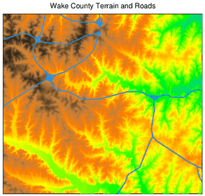
Figure: Result of for the a simple Wake county terrain and roads example
More complicated example
The following is content of a file named elevation_map.txt:# this ps.map example draws a map of Wake county, NC raster elevation colortable y where 1 6.0 cols 4 width 4 font Helvetica end setcolor 6,8,9 white setcolor 10 green vlines streams width 0.1 color blue masked n label streams end vlines roadsmajor width 1.5 style 1111 color grey masked n label major roads end vlegend where 4.5 0 font Courier fontsize 8 end text 30% 100% Wake County Terrain color black width 1 background white size 550 ref lower left end text 92% -25% meters color black width 1 background white size 550 ref lower left end scale 1:125000 scalebar f where 1.5 5.5 length 5000 height 0.05 segment 5 numbers 5 end geogrid 60 s color gray numbers 2 black end paper a4 end end
# First set the region
g.region raster=elevation

# Generate map as Postsript file
ps.map input=elevation_map.txt output=elevation.ps
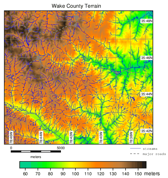
Figure: Result of for the more complicated Wake county, NC example
More examples can be found on the GRASS Wiki help site.
SEE ALSO
g.gui.psmap, g.region, v.label, wxGUI,AUTHOR
Paul Carlson, USDA, SCS, NHQ-CGISModifications: Radim Blazek, Glynn Clements, Bob Covill, Hamish Bowman
SOURCE CODE
Available at: ps.map source code (history)
Latest change: Thursday Oct 01 17:35:27 2020 in commit: 744fcaefa6aa37121e72a9530e90b48fa07bef3a
Main index | PostScript index | Topics index | Keywords index | Graphical index | Full index
© 2003-2023 GRASS Development Team, GRASS GIS 7.8.9dev Reference Manual