Note: This document is for an older version of GRASS GIS that will be discontinued soon. You should upgrade, and read the current manual page.
NAME
i.ortho.photo - Menu driver for the photo imagery programs.KEYWORDS
imagery, orthorectify, geometrySYNOPSIS
Flags:
- --help
- Print usage summary
- --verbose
- Verbose module output
- --quiet
- Quiet module output
- --ui
- Force launching GUI dialog
Parameters:
- group=name [required]
- Name of imagery group for ortho-rectification
- productname=string [required]
- Name of Modules
- Options: i.group, i.ortho.target, i.ortho.elev, i.ortho.camera, g.gui.photo2image, i.ortho.init, g.gui.image2target, i.ortho.rectify
- i.group: 1 - Select/Modify imagery group
- i.ortho.target: 2 - Select/Modify imagery group target
- i.ortho.elev: 3 - Select/Modify target elevation model
- i.ortho.camera: 4 - Select/Modify imagery group camera
- g.gui.photo2image: 5 - Compute image-to-photo transformation
- i.ortho.init: 6 - Initialize exposure station parameters
- g.gui.image2target: 7 - Compute ortho-rectification parameters
- i.ortho.rectify: 8 - Ortho-rectify imagery files
Table of contents
DESCRIPTION
i.ortho.photo is a menu to launch the different parts of the ortho rectification process of aerial imagery. i.ortho.photo allows the user to ortho-rectify imagery group files consisting of several scanned aerial photographs (raster maps) of a common area. i.ortho.photo guides the user through 8 steps required to ortho-rectify the raster maps in a single imagery group. Alternatively, all the steps can be performed separately by running the appropriate modules.- Initialization Options
- Create/Modify imagery group to be orthorectified: i.group
- Select/Modify target location and mapset for orthorectification: i.ortho.target
- Select/Modify target elevation model used for orthorectification: i.ortho.elev
- Create/Modify camera file of imagery group: i.ortho.camera
- Transformation Parameters Computation
- Compute image-to-photo transformation: g.gui.photo2image
- Initialize parameters of camera: i.ortho.init
- Compute ortho-rectification parameters from ground control points: g.gui.image2target
- Ortho-rectification
- Ortho-rectify imagery group: i.ortho.rectify
The ortho-rectification procedure in GRASS GIS places the image pixels on the surface of the earth by matching the coordinate system of the aerial image in pixels (image coordinate system) and the coordinate system of the camera sensor in millimetres (photo coordinate system) for the interior orientation of the image, and further to the georeferenced coordinate system defined by projection parametres (target coordinate system) for exterior orientation.
EXAMPLE
Five groups of input parameters are required for ortho-rectification:- Aerial image (images),
- Exposure and characteristics of the camera, i.e. its coordinates in target coordinate system and height above sea level, focal length, yaw, pitch and roll, dimensions of the camera sensor and resolution of aerial images,
- Reference surface, i.e. digital elevation model in the target coordinate system used to normalize the terrain undulation,
- Topographic reference map used to find corresponding ground control points and/or,
- Coordinates of ground control points in the target coordinate system.
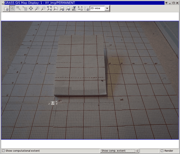
Example of an input oblique image in a source location
To ortho-rectify aerial images the user has to follow the menu options step by step. Alternatively, all the steps can be performed separately by running the corresponding modules.
The aerial photos shall be stored in a source location - a general Cartesian coordinate system (XY). Digital elevation model and a map reference (topo sheet or other map used for ground control point matching) shall be stored in a target location in a real-world coordinate system (e.g. ETRS33).
The steps to follow are described below:
- Create/Modify imagery group to be orthorectified:
i.group
This step is to be run in the source location.
In this first step an imagery group of aerial images for ortho-rectification is created or modified. The current imagery group is displayed at the top of the menu. You may select a new or existing imagery group for the ortho-rectification. After choosing this option you will be prompted for the name of a new or existing imagery group. As a result, a new file mapset/group/name_of_group/REF is created that contatins the names of all images in a group.
IMG_0020 source_mapset
IMG_0021 source_mapset
IMG_0022 source_mapset
- Select/Modify target location and mapset for orthorectification:
i.ortho.target
This step is to be run in the source location.
The target location and mapset may be selected or modified in Step 2. You will be prompted for the names of the projected target location and mapset where the ortho-rectified raster maps will reside. The target location is also the location from which the elevation model (raster map) will be selected (see Step 3). In Step 2, a new file mapset/group/name_of_group/TARGET is created contatining the names of target location and mapset.
ETRS_33N
target_mapset
- Select/Modify target elevation model used for orthorectification:
i.ortho.elev
This step is to be run in the source location.
Step 3 allows you to select the raster map from the target location to be used as the elevation model. The elevation model is required for both the computation of photo-to-target parameters (Step 6) and for the ortho-rectification of the imagery group files (Step 8). The raster map selected for the elevation model should cover the entire area of the image group to be ortho-rectified. DTED and DEM files are suitable for use as elevation model in the ortho-rectification program. In Step 3 you will be prompted for the name of the raster map in the target location that you want to use as the elevation model. As a result of this step, a new file mapset/group/name_of_group/ELEVATION is created contatining the name and mapset of the chosen DEM.
elevation layer :ELEVATION
mapset elevation:target_mapset
location        :ETRS_33N
math expression :(null)
units           :(null)
no data values  :(null)
- Create/Modify camera file of imagery group:
i.ortho.camera
This step is to be run in the source location.
In Step 4 you may select or create a camera reference file that will be used with the current imagery group. A camera reference file contains information on the internal characteristics of the aerial camera, as well as the geometry of the fiducial or reseau marks. The most important characteristic of the camera is its focal length. Fiducial or reseau marks locations are required to compute the scanned image to photo coordinate transformation parameter (Step 5). Two new files are created in this step: a file mapset/group/name_of_group/CAMERA, contatining the name of the reference camera and a file mapset/camera/name_of_reference, contatining the camera parameters.
CAMERA NAME sony CAMERA ID 123 CAMERA XP 0 CAMERA YP 0 CAMERA CFL 16 NUM FID 4 0 -11.6 0 1 0 7.7 2 11.6 0 3 0 -7.7 - Compute image-to-photo transformation:
g.gui.photo2image
This step is to be run in the source location.
The scanned image to photo coordinate transformation parameters, i.e. the "interior orientation", is computed in Step 5. In this interactive step you associate the scanned reference points (fiducials, reseau marks, etc.) with their known photo coordinates from the camera reference file. A new file mapset/group/name_of_group/REF_POINTS is created, contatining a list of pairs of coordinates in image and photo coordinate systems.
# Ground Control Points File
#
# target location: XY
# target mapset: source_mapset
# source  target  status
# east north east north (1=ok, 0=ignore)
#-------------------------------------------------------------
0 1816     -11.6 0.0     1
2728 3632     0.0 7.7     1
5456 1816     11.6 0.0     1
2728 0.0     0.0 -7.7     1
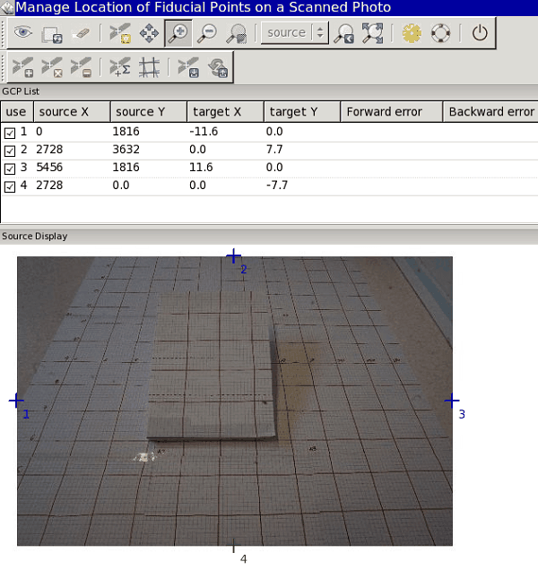
Step 5: Image-to-photo transformation of an oblique image - Initialize parameters of camera:
i.ortho.init
This step is to be run in the source location.
In Step 6, initial camera exposure station parameters and initial variances may be selected or modified.
- X: East aircraft position;
- Y: North aircraft position;
- Z: Flight heigh above surface;
- Omega (pitch): Raising or lowering of the aircraft's front (turning around the wings' axis);
- Phi (roll): Raising or lowering of the wings (turning around the aircraft's axis);
- Kappa (yaw): Rotation needed to align the aerial photo to true north: needs to be denoted as +90° for clockwise turn and -90° for a counter-clockwise turn.
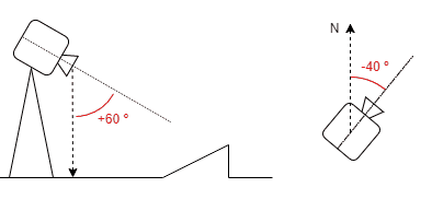
Principle of pitch and yawIn Step 6, a new file mapset/group/name_of_group/INIT_EXP is created, contatining camera parameters.
INITIAL XC    215258.345387
INITIAL YC    6911444.022270
INITIAL ZC    1101.991120
INITIAL OMEGA 0.000000
INITIAL PHI   -0.168721
INITIAL KAPPA 3.403392
VARIANCE XC    5.000000
VARIANCE YC    5.000000
VARIANCE ZC    5.000000
VARIANCE OMEGA 0.000000
VARIANCE PHI   0.020153
VARIANCE KAPPA 0.017453
STATUS (1=OK, 0=NOT OK) 0
- Compute ortho-rectification parameters from ground control points:
g.gui.image2target
This step is to be run in the target location.
The photo to target transformation parameters, i.e. the "exterior orientation", is computed in Step 7. In this interactive step, control points are marked on one or more imagery group files and associated with the known standard (e.g. UTM) and elevation coordinates. Reasonable rectification results can be obtained with around twelve control points well distributed over the image. In this step, a new file mapset/group/name_of_group/CONTROL_POINTS is created, contatining a list of pairs of coordinates of ground control points in photo and target coordinate systems.
# Ground Control Points File
#
# target location: ETRS_33N
# target mapset: target_mapset
#	source                          target                     status
#	east	north	height          east	north	height    (1=ok, 0=ignore)
#------------------------------     ----------------------    ---------------
98.3679932698 906.327649515 0.0 	1.0 5.0  100.0             1
733.293023813 1329.61100321 0.0 	2.0 6.0  100.0             1
1292.6317412  1703.76325335 0.0 	3.0 7.0  100.0             1
1625.54617472 1368.11694482 0.0 	4.0 6.0  100.3             1
3239.82849913 1390.97403968 0.0 	7.4 6.0  100.3             1
1570.09788497 2790.06537829 0.0 	3.0 11.0 100.0             1
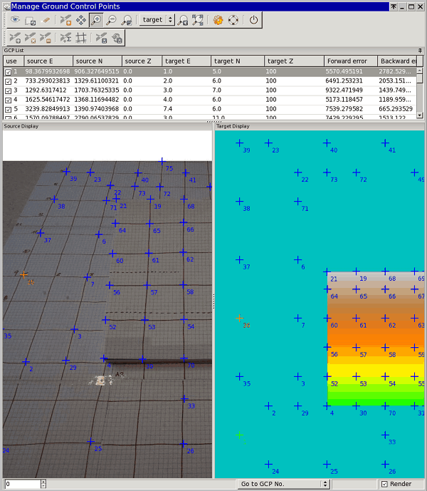
Step 7: Detail of ground control points matching in an oblique image and terrain model - Ortho-rectify imagery group:
i.ortho.rectify
This step is to be run in the source location.
Step 8 is used to perform the actual image ortho-rectification after all of the transformation parameters have been computed. Ortho-rectified raster files will be created in the target location for each selected imagery group file. You may select either the current window in the target location or the minimal bounding window for the ortho-rectified image.
As a result, the ortho-rectified raster map is available for visualization and further image analysis.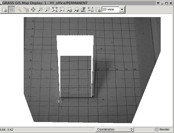
Step 8: Ortho-rectified oblique image
REFERENCES
Wolf P.R. (1983). Elements of Photogrammetry: With Air Photo Interpretation and Remote Sensing McGraw Hill Higher Education ISBN-10: 0070713456, ISBN-13: 978-0070713451SEE ALSO
g.gui.image2target, g.gui.photo2image, i.group, i.ortho.camera, i.ortho.elev, i.ortho.init, i.ortho.rectify, i.ortho.targetAUTHORS
Mike Baba, DBA Systems, Inc.GRASS development team, 199?-2017
SOURCE CODE
Available at: i.ortho.photo source code (history)
Latest change: Wednesday Feb 09 22:41:37 2022 in commit: c37871b51d202b155b64ba04288c4242826936f2
Note: This document is for an older version of GRASS GIS that will be discontinued soon. You should upgrade, and read the current manual page.
Main index | Imagery index | Topics index | Keywords index | Graphical index | Full index
© 2003-2023 GRASS Development Team, GRASS GIS 8.2.2dev Reference Manual